

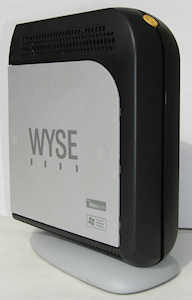
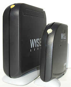
The WT9450XE is a 'fat' thin client! It is physically larger than most thin clients. The picture above on the right shows it alongside the smaller the WT3150SE/WT3125SE. On looking inside the reason for its size becomes apparent - it is using a standard EPIA mini-itx motherboard. [May 2015: Link removed as no longer current] VIA's marketing blurb for this is:
The VIA EPIA Mini-ITX mainboard brings the industry's smallest, most highly integrated, and most flexible x86 platform to OEMs and System Integrators looking for solutions that offer the maximum of features without sacrificing design flexibility. Offering the choice of a VIA Eden ESP processor core for fanless systems with power sensitive requirements, or a VIA C3 E-Series processor for more multimedia rich applications, the EPIA Mini-ITX mainboard also features embedded onboard graphics and audio support. The VIA EPIA Mini-ITX mainboard is the ideal platform for an almost unlimited variety of Extreme Value PC, Information Appliance, Set Top Box, Personal Video Recorder, and Industrial PC designs.
Measuring just 170mm x 170mm, the VIA EPIA Mini-ITX mainboard is 30% smaller than the smallest Flex-ATX platforms, while maintaining Micro ATX chassis compliancy. It also provides the smallest and coolest processing environment available, including an optional fanless configuration. The VIA Apollo PLE133 North Bridge features integrated graphics with 2D/3D acceleration and Motion Compensation, accompanied by onboard SoundBlaster and SoundBlaster Pro compatible audio, delivering key multimedia capabilities. Onboard 10/100 LAN, an additional PCI slot, and a full set of I/O features provide ample connectivity and expansion options.
My 9450XE was manufactured in December 2002.
The basic specs are:
Processor Type
SpeedVIA C3 Samuel 2
550MHzMemory Flash
RAM256MB
256MB (512MB max)Video Chip
Resolutionintegrated Trident Blade 3D
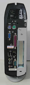
1024 x 768 @ 32-bit colourPorts Network
USB
Serial
Parallel
PS/210/100
2 x USB1.1
1
1
2 (Kybd & Mouse)Power Plug
Off
RunningCoax 5.5mm/2.1mm
7 W
14WDimensions H x W x D (mm) 270 x 75 x 200 (foot pushed width to 103) The embedded operating system is Windows XPe SP1.
For those to whom it matters here is some detail from Linux's /proc/cpuinfo
vendor_id : CentaurHauls cpu family : 6 model : 7 model name : VIA Samuel 2 stepping : 3 flags : fpu de tsc msr cx8 mtrr pge mmx 3dnow up
00:00.0 Host bridge: VIA Technologies, Inc. VT8601 [Apollo ProMedia] (rev 05)
00:01.0 PCI bridge: VIA Technologies, Inc. VT8601 [Apollo ProMedia AGP]
00:11.0 ISA bridge: VIA Technologies, Inc. VT8231 [PCI-to-ISA Bridge] (rev 10)
00:11.1 IDE interface: VIA Technologies, Inc. VT82C586A/B/VT82C686/A/B/VT823x/A/C PIPC Bus Master IDE (rev 06)
00:11.2 USB Controller: VIA Technologies, Inc. VT82xxxxx UHCI USB 1.1 Controller (rev 1e)
00:11.3 USB Controller: VIA Technologies, Inc. VT82xxxxx UHCI USB 1.1 Controller (rev 1e)
00:11.4 Bridge: VIA Technologies, Inc. VT8235 ACPI (rev 10)
00:11.5 Multimedia audio controller: VIA Technologies, Inc. VT82C686 AC97 Audio Controller (rev 40)
00:12.0 Ethernet controller: VIA Technologies, Inc. VT6102 [Rhine-II] (rev 51)
01:00.0 VGA compatible controller: Trident Microsystems CyberBlade/i1 (rev 6a)
 The unit requires a 12V supply and uses a standard 5.5mm/2.1mm coaxial connector.
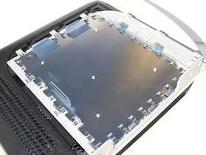
The Wyse thin clients aren't always the easiest to take apart as the plastic housings have various hidden catches that aren't always the easiest to reach. With the 9450 the obvious approach is actually the correct one. The grey cover does actually slide to the rear once you've lifted the latch at the back. However underneath the grey panel is the usual steel panel, metal fingers etc that engage with the main housing. Net result is that it is extremely reluctant to move. I ended up shifting it slowly with some assistance from a flat-bladed screwdriver at the front edge of the panel - providing a bit of leverage between the grey and black plastic. You need to do this with some caution otherwise you'll mark/damage the plastic.
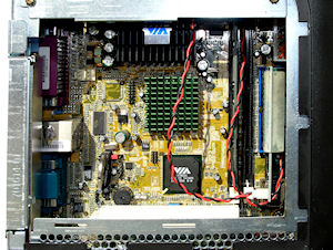
 Almost everything you need to know is in the motherboard manual.
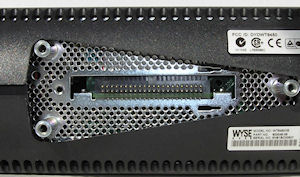
Flash: The flash is a DOM plugged into the second of the two 40-pin IDE connectors. The first connector is actually routed via a small adaptor board (which adds the +5V supply) to a 44-pin socket on the bottom of the unit which is hidden under the foot - see photo right. I did try plugging a 2.5" drive into this but it didn't work. Subsequently I discovered that the plug on the end of the internal cable hadn't been pushed fully home into the socket in the foot.
RAM: The RAM is a conventional stick of 168-pin PC133 SDRAM plugged into one of the two DIMM sockets. According to the manual each DIMM socket will take up to 512MB DIMMs giving a 1GB maximum (2x512MB).
PCI: There is a small riser board carrying a PCI socket so that a small expansion board can be added - such as another ethernet interface, wireless LAN card or USB2.0/USB3.0 interface card.
What with the PCI slot and the available internal space there is considerable scope to turn this into a useful appliance of some kind. If you want to go wireless then a PCI card would be the way to do it as that would avoid the bottleneck of the USB 1.1 interface.
Internal disk drive: It's actually a simple matter to fit one. Click on the mods tab above.
Click on the photo for a closer look at the internal hardware.