

For the Neoware thin clients there is a handy document from HP which you can use to identify exactly what you have. In my case the label on the back of the unit reads CA15 with a part number of BV-01-CC. This breaks down as:
BV Product Line G160 (The circuit board inside the box) 0 Software Standard software 1 Platform 1 = CE.NET C Flash Capacity C = 32Mb C RAM Capacity C = 128Mb
Apparently CA15 is the Bcom number, the marketing number being C50.
The basic specs are:
Processor Type
SpeedVIA Samuel 2
400MHzMemory Flash
RAM32M (max 1024M)
128MB (max 512MB?)Video Chip
Max resolutionVIA VT8623 (Apollo CLE266)
1600 x 1200 32-bit colourPorts Network
USB
Serial
Parallel
PS/210/100
2 x USB2.0
1
1
Kybd & mousePower Off
Running0 W
14-18W
Unlike a lot of other thin clients the Neoware CA15 has an internal power supply. The mains lead has a "clover leaf" style connector rather than the more usual kettle style. If your CA15 came without a lead these are easy to source.
VIA's processors seem to be loosely named. C7/C3/Eden etc actually cover a range of capabilities. For those to whom it matters here is some detail from Linux's /proc/cpuinfo
vendor_id : CentaurHauls cpu family : 6 model : 7 model name : VIA Samuel 2 stepping : 3
Both the Flash memory and the RAM in the CA15 are easily replaceable. (Note: Click on the image of the inside of the CA15 for a larger view).
Flash: The flash is a "DiskOnModule" that interfaces via a 44-pin IDE connector. The system will quite happily boot from a Compact Flash card or 2.5" drive connected in its place.
RAM: The RAM is a 200-pin DDR SODIMM. I haven't been able to locate an actual specification for what the CA15 supports, but the 128MB module fitted is a DDR400 (PC3200) unit manufactured by pqi. I have successfully replaced it with 256MB module that I had to hand - the replacement only being DDR333. Michael Steele emailed to say that he's successfully installed 512MB - Crucial Part Number CT807983 (PC2700).
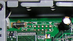 USB: Teun Kloosterman emailed me to point out that the PCB has an area adjacent to the
DOM which is labelled USB1 (see photo for detail). Unlike the CA19 there is no header fitted to it.
He soldered in a header and found he'd gained an extra USB port.
USB: Teun Kloosterman emailed me to point out that the PCB has an area adjacent to the
DOM which is labelled USB1 (see photo for detail). Unlike the CA19 there is no header fitted to it.
He soldered in a header and found he'd gained an extra USB port.
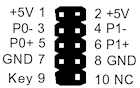 Motherboard USB pinouts are usually(?) as shown left. In this case we we only have a single USB port
tracked out to the connector and so it's only the row of pins nearest the edge of the circuit board
that are used. Pin 1 is clearly marked with a white arrow-head.
Motherboard USB pinouts are usually(?) as shown left. In this case we we only have a single USB port
tracked out to the connector and so it's only the row of pins nearest the edge of the circuit board
that are used. Pin 1 is clearly marked with a white arrow-head.
Having soldered in the header Teun got a little inventive:
"Now I took a cheap USB stick apart and soldered a flat cable to it. Covered it in shrink wrap and taped it to the small removable cover. On the other side I made a 4 pin molex connector et voila I now have 2 GB more storage inside."
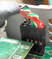
I soldered in a header but took an easier approach to checking it out. Digging around I found an old motherboard-to-backpanel USB connector and used that (see photo below). If you don't have one to hand you can find such things on ebay or elsewhere - it's just a matter of finding the right search term. Having a look just now I found "USB header" was moderately successful.
There is space inside to coil up the cable and to accommodate the socket (less backpanel!) and pendrive. Over the years I'm sure I've seen USB backpanel-to-motherboard connectors where the cabling has been to two single strip connectors rather than the two cables going into a single DIL connector which is the example shown below.
Compact Flash Socket: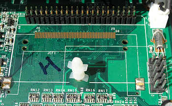 If you look at the circuit board by the 44-pin IDE connector you can see that it is actually tracked
for a Compact Flash card socket. Caleb Mayfield noticed this and decided to get adventurous. He sourced
a suitable socket from Mouser Electronics and soldered it to
the board - see second picture. It works well. He used a 3M part number N7E50-Q516RB-50-WF.
Google should help you find an in-country supplier.
If you look at the circuit board by the 44-pin IDE connector you can see that it is actually tracked
for a Compact Flash card socket. Caleb Mayfield noticed this and decided to get adventurous. He sourced
a suitable socket from Mouser Electronics and soldered it to
the board - see second picture. It works well. He used a 3M part number N7E50-Q516RB-50-WF.
Google should help you find an in-country supplier.
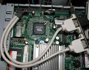
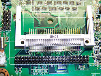 Sorry about the mixed orientation of the two photos. The 'before' picture is of my CA15 whilst the
'after' picture is from Caleb. His motherboard was out of the case at that time and I didn't have the
energy to dismantle mine that far just for the photograph. Net result is that there is a 180 degree
difference between the two views, but I'm sure you can sort that out.
In my photograph the support pillar for the flash module is also still in place - you obviously
need to remove that in order to insert a Compact Flash card into your new socket!
Sorry about the mixed orientation of the two photos. The 'before' picture is of my CA15 whilst the
'after' picture is from Caleb. His motherboard was out of the case at that time and I didn't have the
energy to dismantle mine that far just for the photograph. Net result is that there is a 180 degree
difference between the two views, but I'm sure you can sort that out.
In my photograph the support pillar for the flash module is also still in place - you obviously
need to remove that in order to insert a Compact Flash card into your new socket!
In each photograph you can also see the added header for the internal USB port.